Sprayer module installation
Figure 5.15 presents the sprayer module with descriptions of the individual elements.

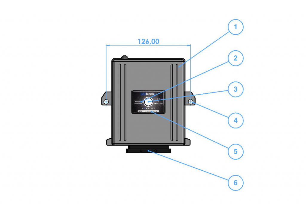
Figure 5.15 Sprayer module with descriptions of external elements. 1 – Module main body; READY control LED; 3 – Module power switch; 4 – d6 mounting hole; 5 – Module SN serial number; 6 – Wiring harness socket;
Install the sprayer module on the sprayer at a location ensuring easy access to the controller power switch for the operator and in a way that allows for the connection of all electric valves and sensors. When choosing the sprayer module location, ensure uninterrupted Wi-Fi communication. Installation of the sprayer module on the back or on the side of the sprayer is not allowed. Installation of the sprayer module in additional boxes is not allowed.
Regardless the configuration kit ordered, the wiring harness is ready for connecting to all the possible sensors and valves supported by the device.
The wiring harness consists of cables that have been described in Figure 5.16.
-
eSpray / eSpray GSM / eSpray GPS Assist
- PIN codes for AutoDrive / eSpray GPS Assist computer
- Sprayer computer - home screen
- Create spraying program
- Spraying program - edit
- Spraying program - select
- Spraying program - delete
- Joystick and section button control
- First start
- Tank filling
- Correction source
- Speed settings
- Pressure settings
- Flowmeter
- Row width adjustment
- Operation of the third section
- Speed simulation
- Pressure settings - sensor calibration
- eSpray controler pinout and harness
- SIM card installation
- Sprayer module installation
- Sprayer computer installation
- Installation guidelines
- Accessories and additional equipement
- Kit components
- Electric valves connection
- Speed sensor installation
- Pressure sensor installation
- Temperature sensor installation
- Flowmeter connection
- Tank level connection - optional
- Fan sprayer tower light connection
- Application rate
- Valves requirements
- LTE (GSM) settings
- PIN for the menu
- Remote support
- Show Remaining Articles (21) Collapse Articles
-
Remote Control
-
EHR - Electronic hitch controler
- No articles
-
Line Assist Pro
- No articles
-
Line Assist for platforms
- No articles
-
AutoDrive
- PIN codes for AutoDrive / eSpray GPS Assist computer
- Quick guide of the AutoDrive system
- Calibration after AutoDrive system installation
- LTE (GSM) settings
- Correction source
- GNSS Receiver configuration
- Safety settings
- LIDAR basic sensor
- Implement / machine settings
- Route recording - spraying
- Autonomous spraying
- Mowing - route recording
- Route recording with mower
- Autonomous grass mowing
- Speed management
- Starting revs
- Constant operating revs
- Revs controlling - Fendt Vario
- Alarms
- Turn definition
- Brake drive calibration
- Remote support
- GNSS status menu
- IMU settings verification
- ROI settings for ODC (Obstacle Detection Camera)
- ROI settings for ODC camera
- Show Remaining Articles (11) Collapse Articles
-
RTK Base station
-
GOtrack Farm Manager
- No articles