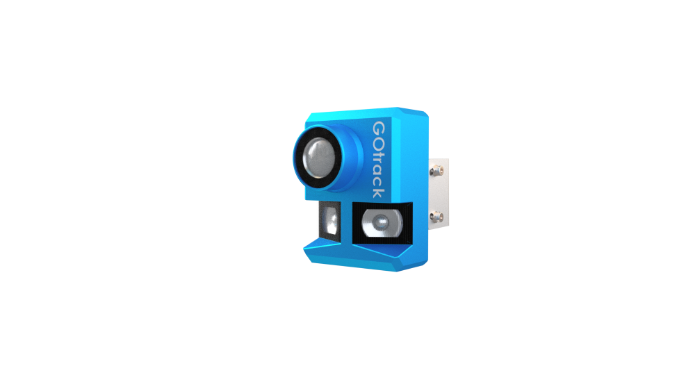
LIDAR basic sensor
GOtrack AutoDrive system is equipped in LIDAR sensor which is installed on the front of the vehicle. Normally sensor is installed together with the front bumper.
Horizontal FOV – 95 degrees.
Vertical FOV – approx. 10 degrees.
Communication with MCU – CANBUS
Power supply – 12VDC
Sensor is responsible for detection of the solid obstacles depending on the settings in the menu. When using system with the remote control to control the tractor from the trailed platform this sensor can be used as Line Assist sensor for row detection and steer the tractor in the center between the rows. When driving tractor remotely safety zones are active too and tractor will stop when obstacle is detected.

LIDAR safety system is only REDUCING the risk of an accident !!!
LIDAR do not provide 100% obstacle detection. Always check the area vehicle is going to drive autonomously. Safety conditions MUST be fullfield before runing the vehicle in AutoDrive mode!!!
Before using the AutoDrive system check safety conditions.
SAFTEY ZONES
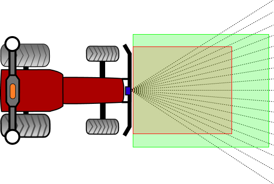
Safety zones are divided into two zones:
- deceleration zone
- stop zone
DECELERATION ZONE
When an object is recognized as an obstacle (detection time and number of beams conditions are fullfield) and that object will be present in deceleration zone then system will slow down the vehicle. When speed control is achieved by engine RPM regulation then system will set minimal RPM level to slow down the vehicle. That means that speed will be dependant on the selected gear. In case speed control is achieved by transmission ratio (Fendt Vario or tracotrs with CVT or hydrostatic transmission – HST), then in case of obstacle detection in deceleration zone system will slow down the vehicle up to 5 km/h.
STOP ZONE
In case an obstacle is detected in stop zone then system will always stop the vehicle.
DETECTION TIME
Detection time is the time that need to elapse when obstacle size (number of beams) conditions are fullfield to slow down or stop the vehicle.
NUMBER OF BEAMS
Sensor FOV is divided into beams. Each beam has 6 degrees of horizontal opening. By selecting number of beams operator sets the size of the object to be recoginized as an obstacle.
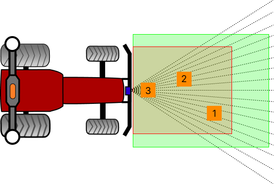
For better understanding of the LIDAR working principle on the picture above there are shown 3 obstacles in different locations. The size of those obstacles is exactly the same but as you can observe location is afecting number of violated beams. For example if number of beams is set to 5 obstacle number 1 and 2 will not stop the vehicle. Only obstacle number 3 will stop it because it is closer to the sensor and it is violating more beams. High number of detection beams will cause that vehicle will stop later – not immediately when the obstacle is in the stop zone.
LIDAR IN TURNS
When the vehicle with AutoDrive system installed on it is turning also LIDAR zones are “turning”. An example of the zone location change is presented on the pictures below.
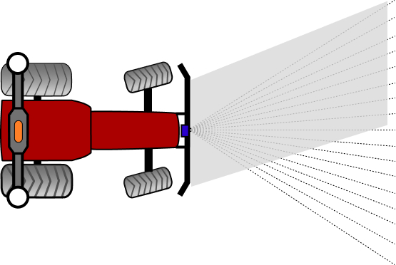
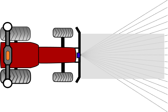
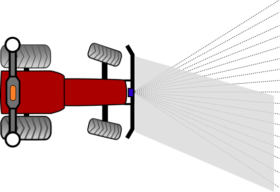
It is important to remember that lidar FOV (Field of View) stays in the same position when vehicle is turning. Only grey rectangle is following the turn. It may happen that when front wheels are fully turned LIDAR visibility will be strongly reduced.
Rectagle reaction strongly depends on settings in the menu FRONT SENSOR:
- maximum turning angle
- LIDAR distance to front axle
If the maximum turning angle is set higher than real truning angle then rectangle will move more then the real path of the vehicle and some obstacles may be missed when turning. When it is set to low then LIDAR can detect obstacles which are not on the vehicle’s path.
LIDAR distance to front axle will change also calculations of rectangle movement.
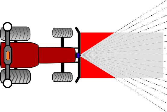
BLIND SPOTS
Since the LIDAR sensor has 95 degrees of horizontal FOV it has some limitations. Closer to the sensor there are blind spots where LIDAR cannot see anything. Red areas marked on the picture below present possible blind spots.
LIDAR SENSITIVITY
Proper sensitivity (reflection treshold) setting is needed for best system performance. Higher value means that LIDAR is detecting only very solid objects. Low value means LIDAR is detecting even small particles like rain drops or dust.
Lower value is mostly used during winter time when sensor is used in Line Assist mode. Then no leaves on the trees require to lower reflection treshold.
LIDAR SETTINGS WITH CONFIGURATION APP
For system settings GOtrack provides Android Configuration App. The app alows to configure LIDAR sensor.
Download confiiguration app from here.