GNSS Receiver configuration
Just after installation or when it is needed GNSS receiver configuration settings must be performed for best system performance.
RECEIVER TYPE
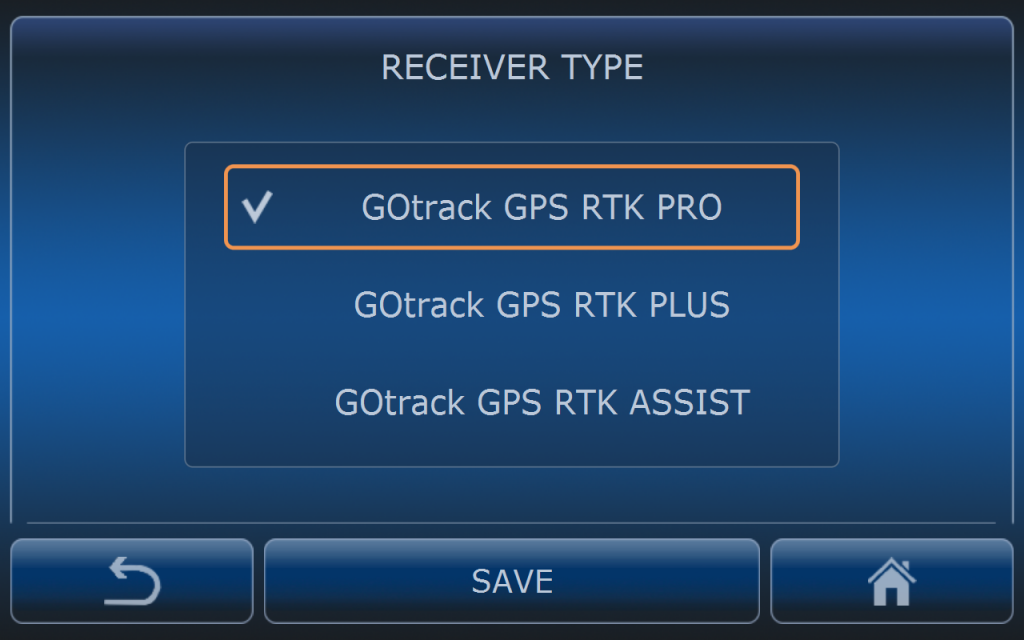
When system is used in autonomous mode GOtrack GPS RTK PRO must be selected which is dual antenna receiver.
GOtrack GPS RTK Assist should be selected when eSpray computer has built-in one antenna receiver. This is not for autonomous driving.
GOtrack GPS RTK PLUS is not used at the moment.
RECEIVER SETTINGS
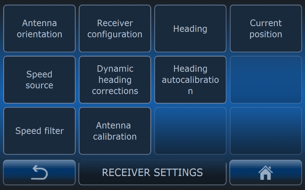
In this menu there is number of GNSS receiver settings. Be very carefull when changing any of setting since it can has critical influence for driving qulity or safety.
ANTENNA ORIENTATION
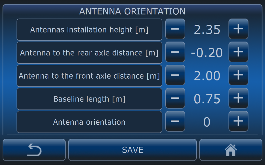
Antenna orientation determines the psoition of the antenna bar on the roof. It is very important to fill these vaules just after installation of the system. Please provide correct measurements and values in this menu so the rest of the calibration porcess will be will be done properly. Wrong values will strongly affect calibration process.
Antenna height has to be measured from the ground to the antenna bar.
Antenna to the rear axle distance is measured from the center point of the antenna bar to the rear axle. When antenna is located between the rear and front axles then these values must be negative. When antenna is located behind the rear axle then this value must be positive. On the picture above antenna is located 20 cm from the rear axle towards front axle.
Antenna to the front axle distance is simillar to the rear axle settings but all measurments are done to the front axle.
Baseline lenght is the distance between the center points of the antennas. Usually antenna distance is 1m or 0.75m but there might be some other variants. Please check the distance after during installation.
Antenna orientation depends on the installation on certain vehicle. On some vehicles it is recommended to install the antenna East-West but when system is used on very narrow tractors then it is good to consider installation in North-South position. There are 4 options for antenna orientation. 0 and 180 is for E-W orientation and 90 and 270 is for N-S orientation. Please check markings on the antenna bar.
It is easy to recognize if the antenna orientation is propper when trying to record new route. When vehicle icon orientation is in proper oreintation with the route then settings are ok.
RECEIVER CONFIGURATION
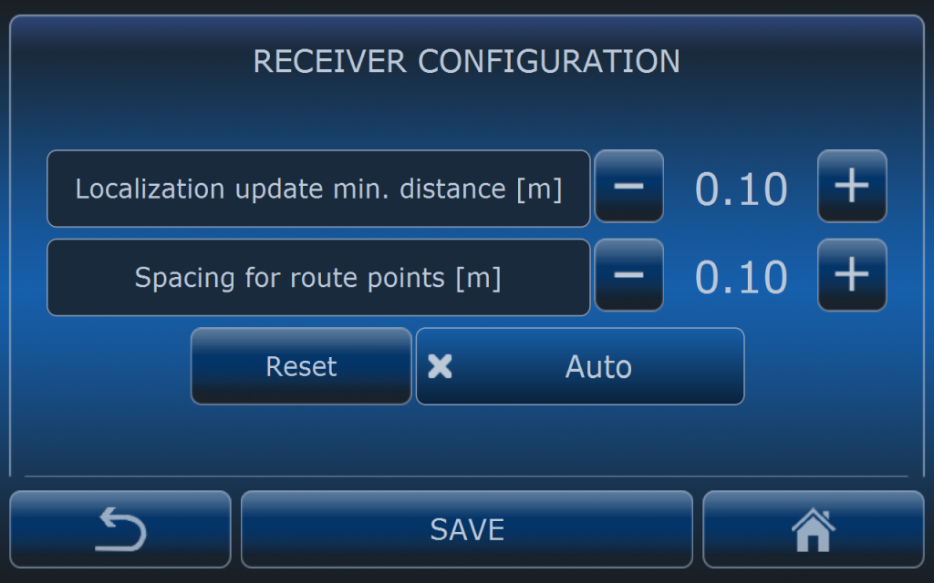
Localization update minimum distance determines how often system is updating position for algorithm calculations whlie driving. By default this value is 10 cm. It means that system is recalculating it’s position and steering commands after 10 cm is passed.
Spacing for route points determines the distance between every point of the route when recording the route.
By default distance is set to 10 cm. When distance is lower route is more precise but map files are getting bigger so loading maps and other processes can became slower.
RESET button is for reseting GNSS receiver without restarting eSpray computer.
AUTO button when activated restarts GNSS automatically receiver when communication is failed for longer time.
HEADING
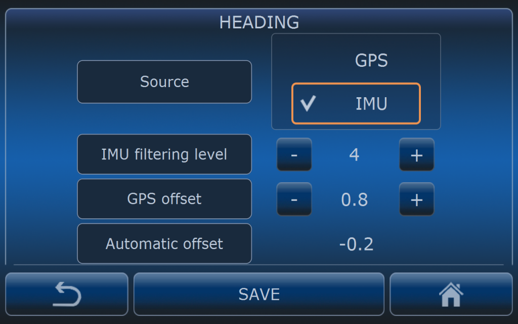
SOURCE determines if heading information is delivered directly from GPS receiver or it is filtered by IMU sensor. By default it IMU filtering is set. When direct GPS source is selected then steering wheel drive can bacome more “nervous”.
IMU filtering level determines how big is the impact of IMU for heading calculation. If the number is higher then heading is dependent more on IMU sensor. When it is lower then heading is more dependant on GPS readings. Default value is 4. Setting filtering level to high values is not recommended because of IMU drift especially when driving slowly.
CURRENT POSITION
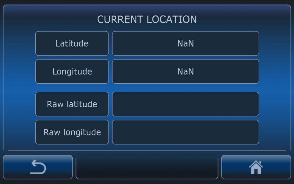
This menu allows to check current position. Only for testing.
SPEED SOURCE
For speed control very good speed source is needed. Depending on the tractor it is important to choose proper speed source.
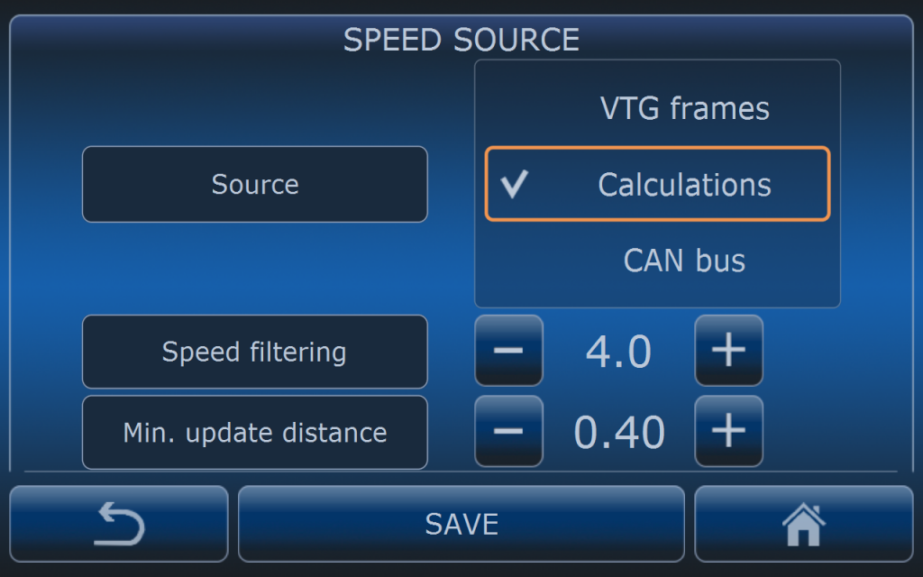
If vehicle does not have CAN-BUS the only way to deliver speed information to the GOtrack system is to set VTG frames or Calculations. Recommended are calculations.
By default Speed filtering is set to 4.0 and minimum update distnace is set to 40 cm. It means that for speed calculations system will be updated every 40 cm.
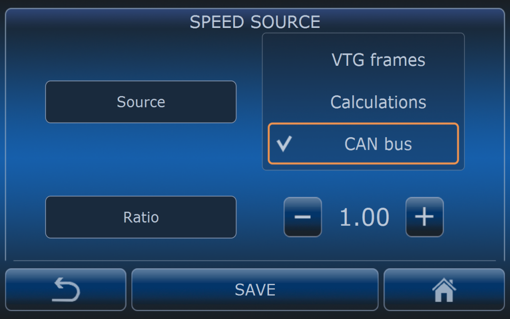
If vehicle is equipped in CAN-BUS and speed information is present in the BUS then this is the best option for speed source. Before selection this option extra settings are needed using GOtrack Configuration App.
After connecting App with MCU go to CAN BUS menu and then VEHICLE SPEED menu to set proper CAN ID frame and other parameters. Only correct settings in this menu guarantee good speed readings.
DYNAMIC HEADING CORRECTIONS
When driving on slopes and hilly terrain it may turn out that tracotr is driving next to the path so some additional corrections are needed. Depending on the terrain conditions user has to find proper settings making some tests.
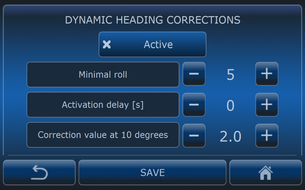
For activating corrections ACTIVE button must be checked.
Minimal roll is the value of the roll from which correction starts to work. Below this value algorithm is not active.
Actiavtion delay is the time after which correction algorithm starts to work if minimal roll condition is fullfield.
Correction value at 10 degrees is the heading correction value when roll reach 10 degrees.
In this example heading correction starts with 0 when roll is 5 degrees and proportioanlly increases to 2 degrees when roll will reach 10 degrees. Above 10 degrees of roll heading correction increment is the same like below 10 degrees.
HEADING AUTOCALIBRATION
Heading autocalibration is algorithm that adjust automaitacally heading of the antenna bar when vehicle is driving. This algorithm provide more precise driving.
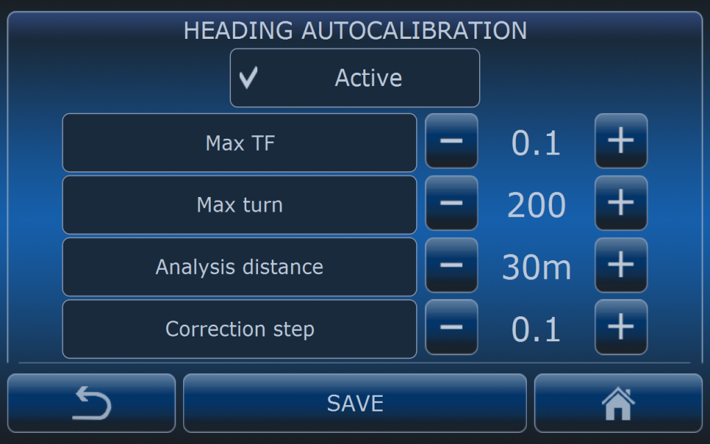
Max TF is the maximum turning factor value of the path at the location of the vehicle (present turn value to maximum turn value ratio). Only below this value heading autocalibration will be performed.
Max turn is the value of present turn value which range is from -1000 to +1000. It means that calibartion will be not performed when steering wheel drive makes turn larger then 200 (20% of turning range from center to one side).
Analysis distance is the distance which has to be driven to make one Corretion step if conditions above are all the time fulfilled.
In this example heading will be corrected autoamatically by 0.1 degree after 30 meters of driving on straight section of the route because TF smaller than 0.1 means that section of the route straight.