Installation guidelines
The sprayer computer is installed inside the tractor cabin on a dedicated d12 mm mounting rod or using an optional bracket with suction cups. Inside the cabin, in the area where the sprayer computer is to be installed, the User is required to prepare a 3-pin power socket (see Figure 5.1) connected by means of an OWY 2×1.0 mm2 cable directly to the tractor battery, protected with a 5×20 mm 2 A ferrule fuse, according to the diagram in Figure 5.2.

Figure 5.1 12 V 3-pin power socket.
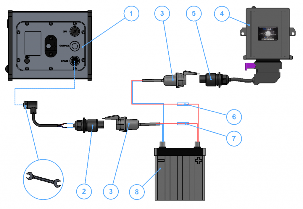
Figure 5.2 Diagram of the computer power supply system; 1 – sprayer computer – rear view; 2 – computer power supply cable; 3 – power supply cable OWY 2×1.0 mm2; 4 – sprayer module; 5 – sprayer module wiring harness; 6 – ferrule fuse 5×20 mm 20 A in the housing; 7 – ferrule fuse 5×20 mm 20 A in the housing; 8 – 12 V tractor battery;
The sprayer module is installed on the sprayer main body near the valve group. The sprayer module is fitted with a power supply cable, terminated with a 12 V 3-pin plug, which should be routed and connected to a 3-pin power socket (see Figure 5.2) to be provided by the user, connected by means of an OWY 2×1.0 cable directly from the tractor battery, protected with a 2 A fuse. The socket should be installed in the rear part of the tractor, near tractor lights.
All the valves that are to be controlled by the device and all the sensors installed on the sprayer are connected to the sprayer module. This is done using the wiring harness.
Conditions to be fulfilled by the Customer prior to device installation
- The sprayer must be operational and in a good technical condition.
- The sprayer must be clean.
- The sprayer hydraulic system must be operational.
- In the tractor dedicated for working with a sprayer equipped with a computer, the user is required to provide two 3-pin power sockets (see Figure 5.1) inside the cabin and in the rear of the tractor, according to guidelines.
- In the tractor cabin, the user is required to prepare a d12 mm mounting rod for sprayer computer installation.
- If an e-Spray GSM device is used, the user is required to provide an operational and registered, standard-size SIM card without a PIN lock. Pre-paid cards are recommended.
- A minimum ambient temperature of +5°C is required for device calibration.
- Following installation and prior to calibration, fill the tank with clean water, bleed the sprayer hydraulic system, use clean spray nozzles and a clean sprayers working liquid filter.
Scope of Seller’s installation works
- Installation of the sprayer module on the sprayer.
- Installation of the speed and pressure sensors on the sprayer.
- Installation of other optional equipment, if ordered.
- Wiring and connecting the sprayer module to the speed and pressure sensors, section valves, control valve, flowmeter, lighting (if present).
- Starting, setting up and calibration of the sprayer computer.
Individual device operating rules user training is provided by the seller serving an individual customer.

Mechanical, hydraulic, electric installation of components, i.e. flowmeter, section valves, control valve, column lighting, other sprayer equipment are not included in the scope of the Seller’s installation works.
The seller shall not responsible for the proper functioning of the hydraulic and mechanic systems of the sprayer and the tractor. In case of unclean nozzles or filter or where the hydraulic system had not been bled, the spraying quantities dosed by the computer may differ from the device indications.