Safety settings
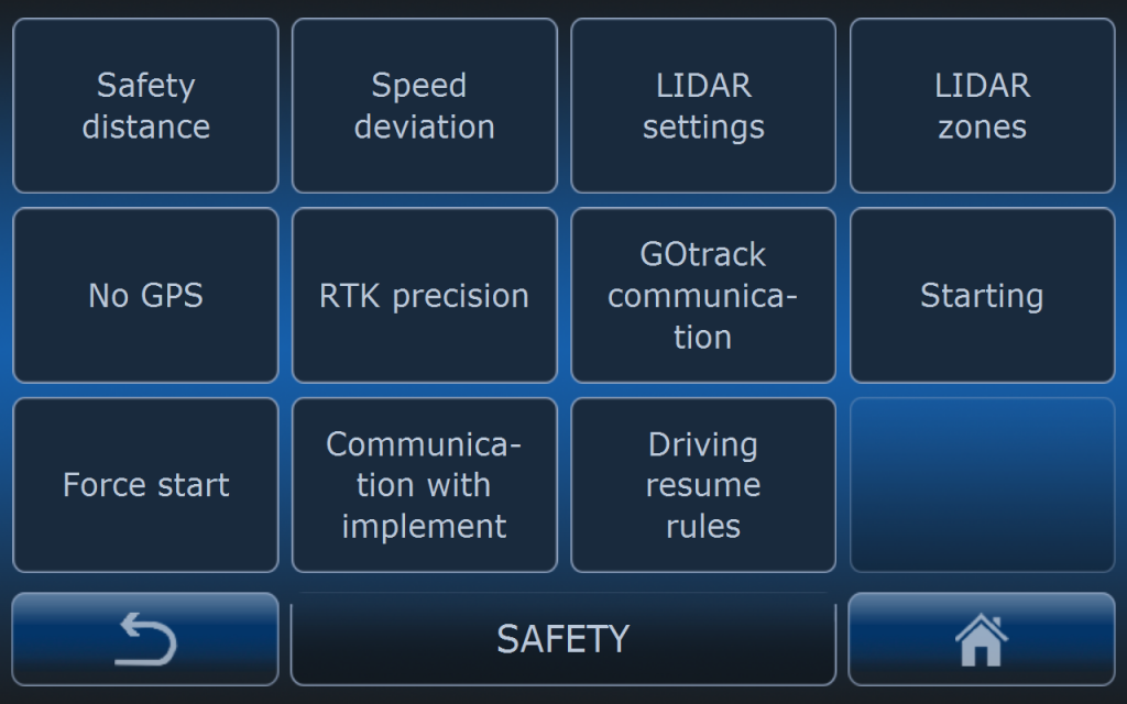

GOtrack AutoDrive system has number of settinngs concerned with safety. Most of these settings have critical importance for safe autonomus operation. Read this manual carefully.
SAFTEY DISTANCE
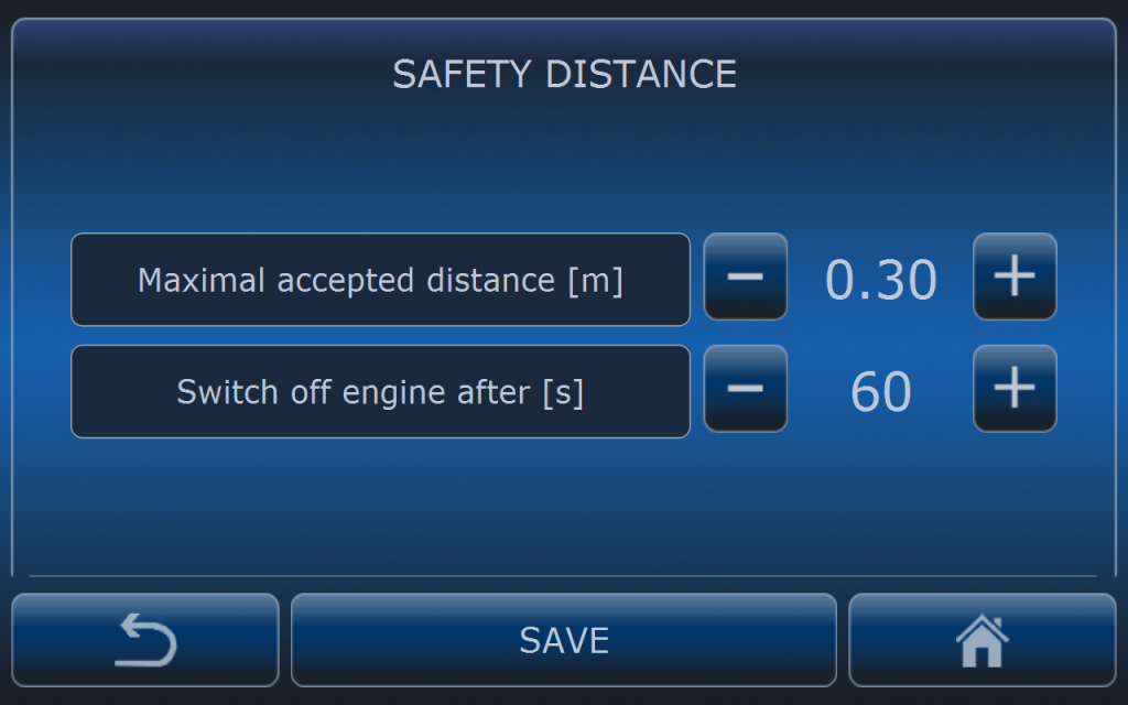
Maximal accepted distance determines how far tractor can go off the path. If this distance is exceeded then tractor will stop immediately. Other functions of the tractor like PTO or hitch will change their status depending on settings. Default value is 25 – 30 cm.
Switch off engine after is the time after which system will switch off the engine. Time is counted from the moment system stopped the tracotr after detecting that safety distance was exceeded. Default value is 60 seconds.
System can try to resume driving automatically but this depeneds on DRIVING RESUME RULES settings which are described below.
SPEED DEVIATION
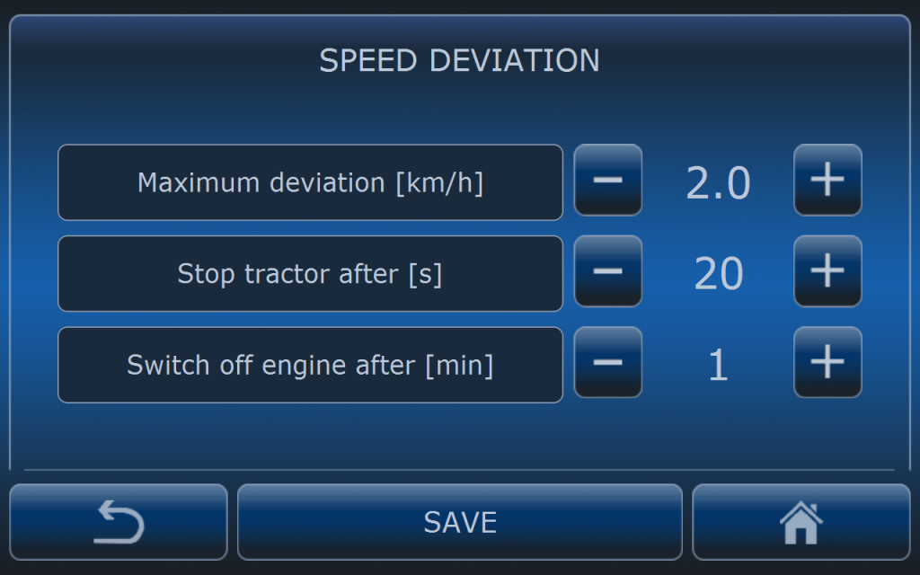
Maximum deviation value determines what is accepted difference in speed from set value and real value. In this example if set speed is 7 km/h system will not stop the tractor if it’s speed is in range of 5 to 9 km/h which is -+2km/h.
Stop tractor after determines the time after which system will stop the tractor from the moment speed deviation condition is fulfilled all that time. Shorter time will cause faster response for speed deviation but also may cause false stops. Default time is 20 seconds.
Switch off engine after is the time after which system will switch off the engine. Time is counted from the moment system stopped the tracotr after detecting speed deviation. Default value is 1 minute.
LIDAR SETTINGS
Each AutoDrive system is eqipped in Lidar sensor for obstacle detection. Depending on the lidar version settings are different. There are two types of lidar sensors:
- basic
- pro
Before reading Lidar settings manual please read article about Lidar basic or Lidar Pro for better understanding working principle of this sesnor.
FRONT SENSOR
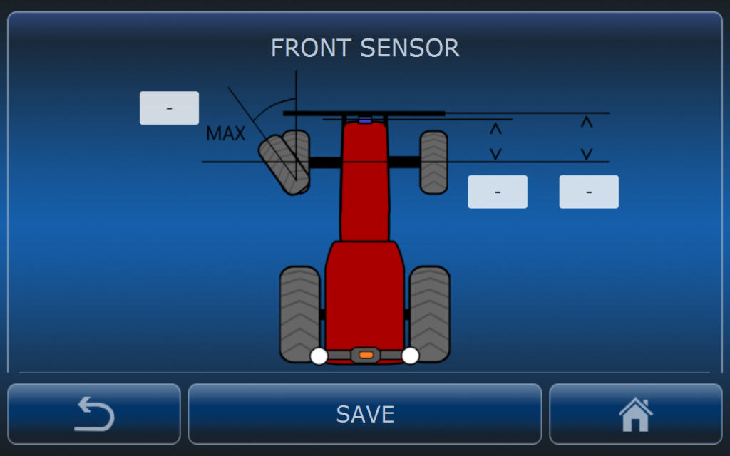
Basic lidar is installed in the front of the vehicle. Usually it is installed on the front safety bumper.
After installation values describing position of the sesnor on the vehicle must be inserted:
- Maximum turning angle
- LIDAR distnace to front axle
- Bumper distnace to front axle
Maximum turning angle value has influence on the displacement of the lidar zones when vehicle is turning left or right. The movement of the zones is described in this article: Lidar basic and it depends on wheel angle sensor. If this value will be higher than real angle then zones will move left and right faster and may not cover real area.
LIDAR distance to front axle also determines displacement of safety zones. If it is not set properly lidar zones may not cover real area in fornt of the tractor that has to be covered.
LIDAR SENSITIVITY
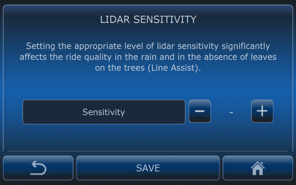
Senistivity is equal to reflection treshold in this case. Range is from 1 to 10.
Low value of senitivity means low reflection treshold. When value is low lidar is detecting objects with lower reflection factor. It means it can “see” more but it may result with detecting some particles in the air and cause false stops (for example msit from the sprayer can be detected). Low values can be used when using this sensor as Line Assist during winter time when there are no leaves on the trees.
In dry and dusty conditions during spring and summer time it is recommended to use high values to avoid detection of dust.
AUTOMATIC DRIVING RESUME
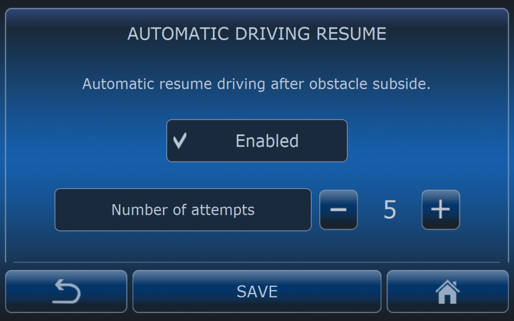
It may happen that system will get into the neverending loop because obstacle detected by lidar is on the edge of detecting treshold.
Example: tractor is driving autonomously. Obstacle is detected and tracotr is stopped. After stopping lidar does not detect any obstacle so system wants to resume driving but at the moment system starts again tractor lidar is detecting obstacle agian so it stops tracotr again and whole cycle will repeat endless.
By enabling this feature system will not loop endless but will try to resume driving 5 times and when it will not succeed it will stop the tractor permamently.
SIDE SENSORS
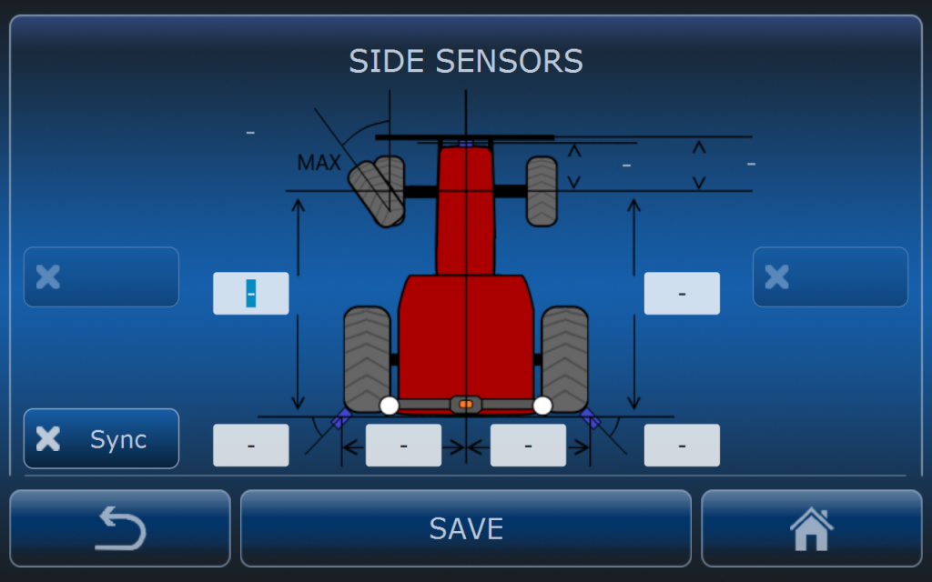
When side sensors are present in the system these settings must be performed for correct system operation.
SENSOR ADAPTATION
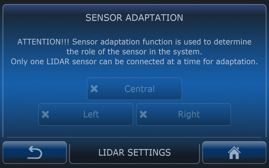
When using basic lidar sesnors it is possible to connect up to 3 sesnors to the MCU: one cetral and two side sensors.
Sensors must be adopted so MCU can recognize them properly. During adaptation process only one sensor can be connected at the time. When sensor is connected to the MCU on this screen present adaptation will be visible. To change present adaptation of the sesnor to the demanded position just press suitable button: central, left or right. When demanded button will be checked it means that adaptation process is finished. To adopt another sensor in the system remeber to disconnect already adopted one.
SENSOR STATUS
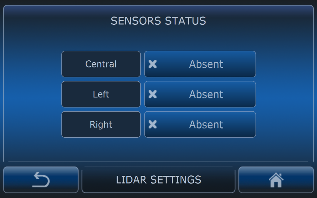
Every sensor sends it’s status to the MCU. On this screen it is possoble to check which sensor is present and recogizned by MCU.
ENGINE SWITCH OFF
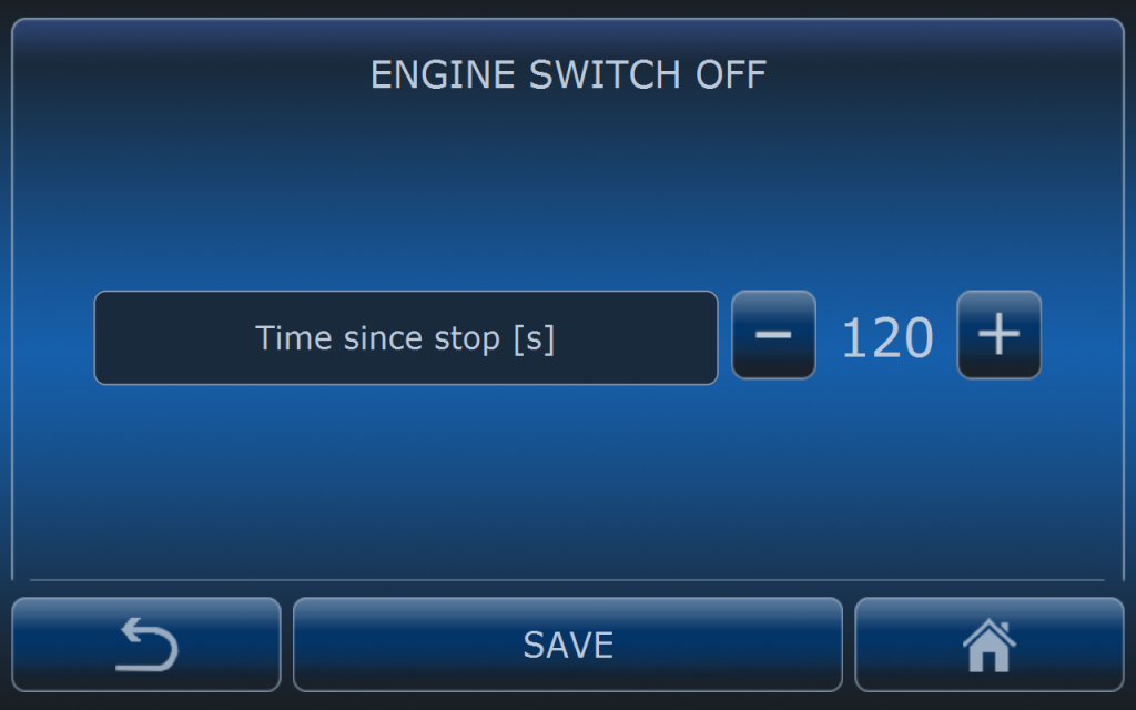
Time to switch off the engine when obstacle is detected and still present in the lidar stop zone.
Default value is 120 second.
LIDAR ZONES
Detailed description of LIDAR zone settings and working principle is in this article. Please read it first for better understanding safety system. Bellow it is only short description of zone settings.
Safety zones are divided into two zones:
- deceleration zone
- stop zone
DECELERATION ZONE
When an object is recognized as an obstacle (detection time and number of beams conditions are fullfield) and that object will be present in deceleration zone then system will slow down the vehicle. When speed control is achieved by engine RPM regulation then system will set minimal RPM level to slow down the vehicle. That means that speed will be dependant on the selected gear. In case speed control is achieved by transmission ratio (Fendt Vario or tracotrs with CVT or hydrostatic transmission – HST), then in case of obstacle detection in deceleration zone system will slow down the vehicle up to 5 km/h.
STOP ZONE
In case an obstacle is detected in stop zone then system will always stop the vehicle.
DETECTION TIME
Detection time is the time that need to elapse when obstacle size (number of beams) conditions are fullfield to slow down or stop the vehicle.
NUMBER OF BEAMS
Sensor FOV is divided into beams. Each beam has 6 degrees of horizontal opening. By selecting number of beams operator sets the size of the object to be recoginized as an obstacle.
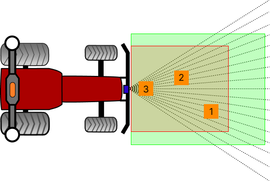
For better understanding of the LIDAR working principle on the picture above there are shown 3 obstacles in different locations. The size of those obstacles is exactly the same but as you can observe location is afecting number of violated beams. For example if number of beams is set to 5 obstacle number 1 and 2 will not stop the vehicle. Only obstacle number 3 will stop it because it is closer to the sensor and it is violating more beams. High number of detection beams will cause that vehicle will stop later – not immediately when the obstacle is in the stop zone.
NO GPS
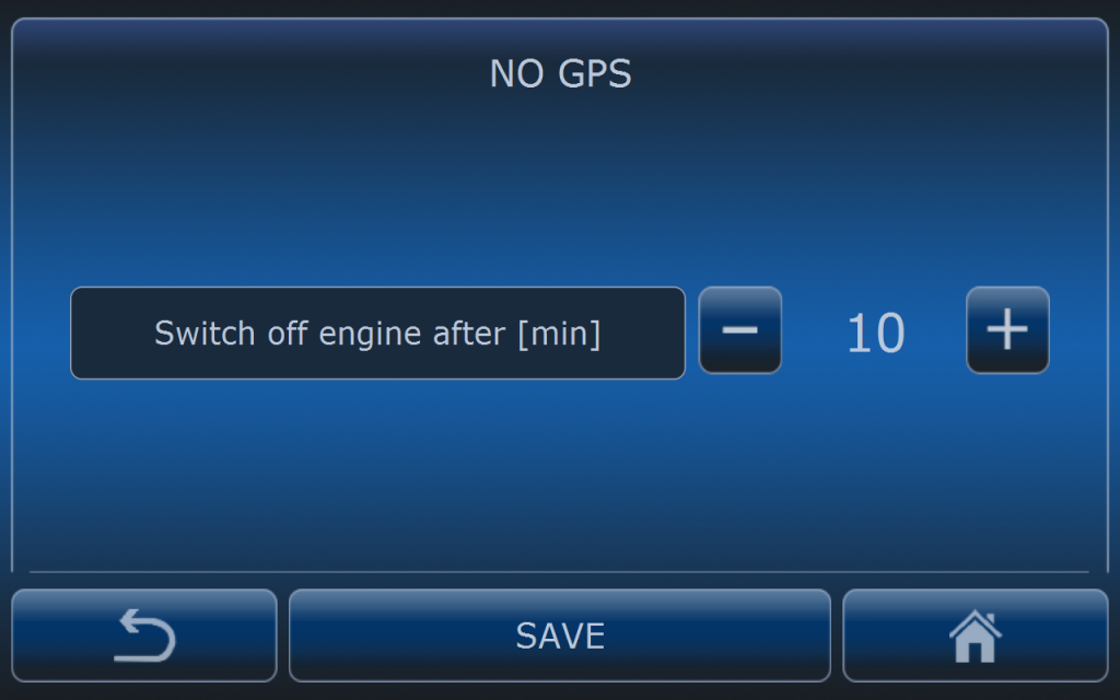
When no GNSS signal is detected then vehicle will be stopped immediately.
Engine will be switched off after 10 minutes (default setting).
RTK PRECISION
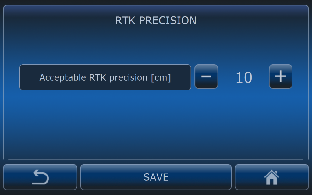
If RTK precision is higher than selected value AutoDrive system will stop the vehicle immediately and it will wait until precision will be better.
If acceptable RTK precision is set to high value (it means low precision is acceptable) then vehicle can drive on the side of the real path. It will not be seen on the computer screen but in real conditions.
Default value is 10 cm.
GOTRACK COMMUNICATION
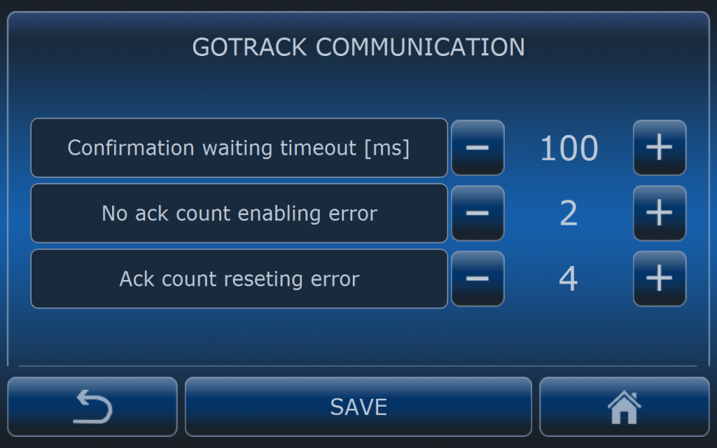
GOtrack MCU and computer installed in the vehicle’s cab are communicating all the time. Computer is expecting confirmation of every information which is sent to the MCU. If confirmation is not received then computer resends same information until it will receive acknowledgment (ACK). If MCU discovers lack of communication system stops immediatelly vehicle if it is driving at the moment and it is waiting untill communication is recovered.
With example settings computer is waiting 100 milliseconds for confirmation. If it is not received it sends same information again. When 2 confirmations in the row are missing then compter reports MCU communication error (GOtrack communication error). If error is present and 4 confirmations in the row are received error disappears and system is able to resume driving.
STARTING
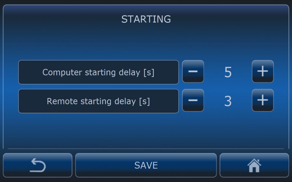
After pressing START button on the computer’s screen or in the app system is counting down the time to start the vehicle.
Computer starting delay is concerned with pressing START button on the computer’s screen.
Remote starting delay is concerned with pressing START button in the app or starting with SMS command.
FORCE START
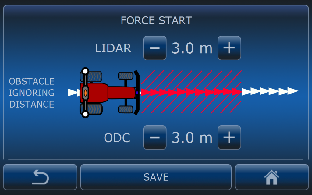
Using ODC camera (obstacle detection camera) and LIDAR can sometimes cause false stops. Since GOtrack app has possibility to show the camera view user is able to force start when an obstacle is not properly detected.
In this menu user can set the distance where all obstacles are ignored when performing FORCE START. If new type of the obstacle is detected then force start will be terminated and vehicle will be stopped again.
COMMUNICATION WITH IMPLEMENT
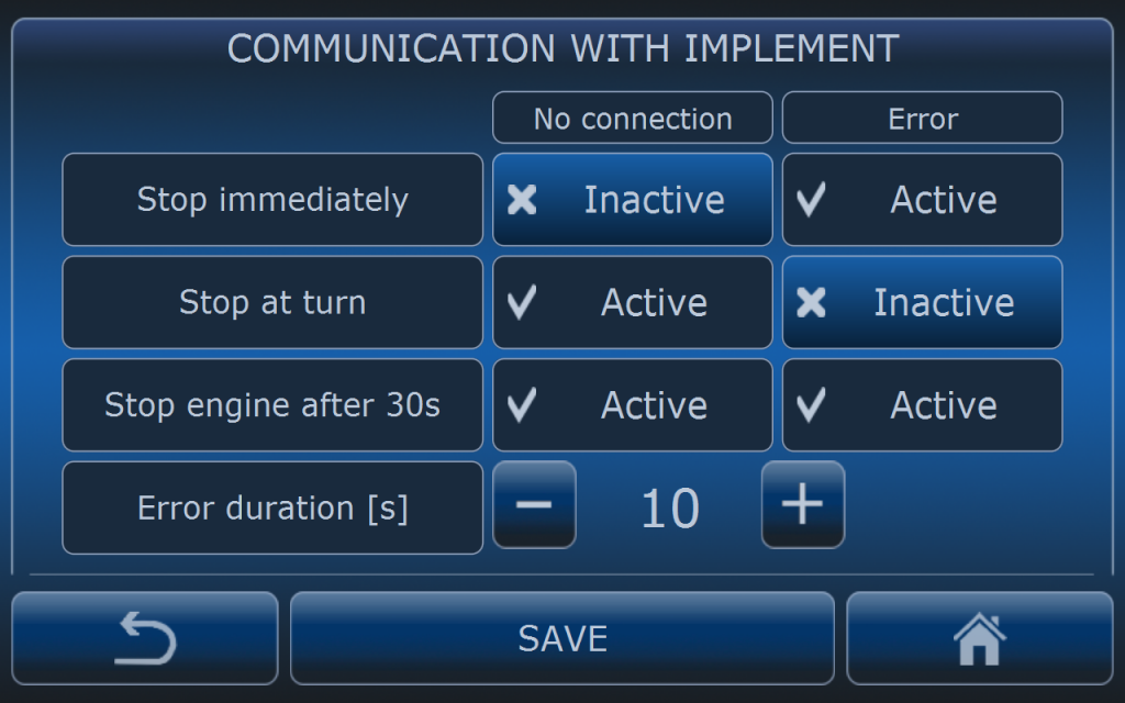
Some implements are controlled with GOtrack control box. There is wireless communication between computer and control box. In case communication is missing system will stop the vehicle to prevent wrong application rates.
In case there is an error implement concerned with i.e. wrong application rate or pressure drop ssytem can also stop the vehicle.
In case of no commuinication or implement error vehicle stop can be performed immediately after time condition is fulfilled (in this example after 10 seconds) or at the neares turn (for better access to the vehicle).
Additionally system can switch off the engine after 30 s if needed.
DRIVING RESUME RULES
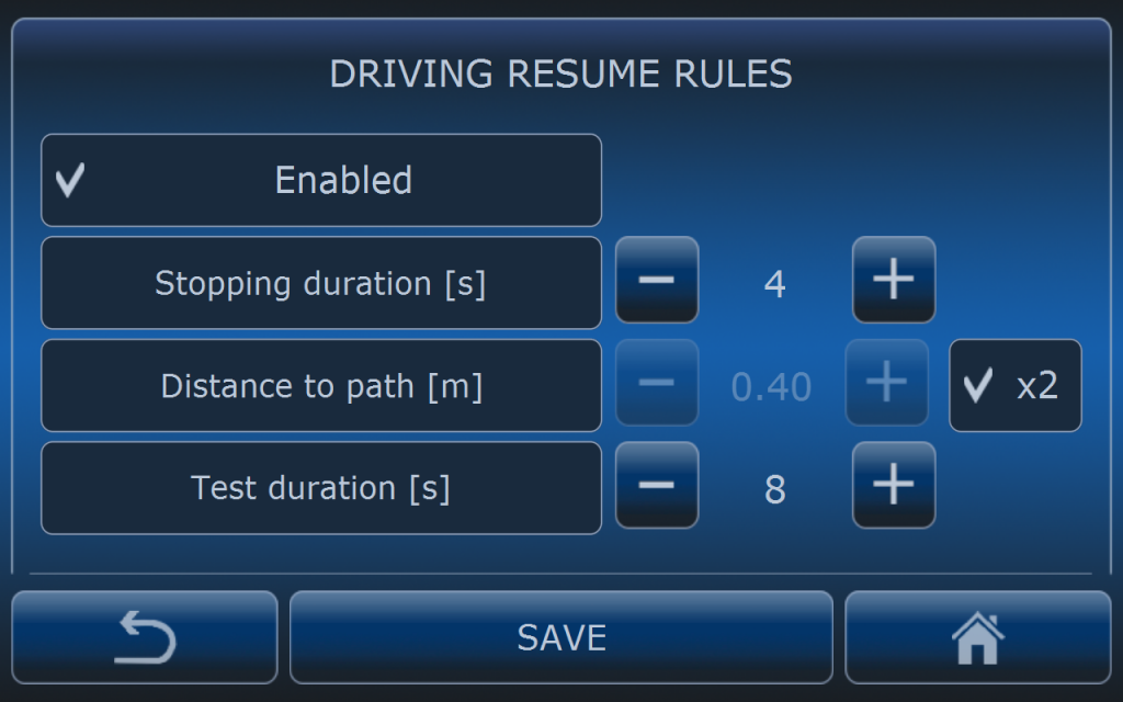
When vehicle is driving in difficult terrain conditions it may happen that it will go off the path (safe distance will be exceeded) and finally system will stop the vehicle. When this functionality is enabled system is able to perform automatic restart when certain and strict conditions are fulfilled.
Stop duration is the time measured from the moement system has stopped the tractor to the moment of performing restart trial. It this example it means tracotr will stop for 4 seconds when it is too far from the path and after that time it wil try to start driving again if distance to path condition is fulfilled too.
Distance to path can be set individually or it can reffer to the safe distance. If x2 button is active it means that distance to path is set to twice safe distance to the path which is set in SAFETY DISTANCE MENU. For example if safe distance is set to 30 cm it means that here it will be 60cm. If distance to path is exceeded at the first stop system will not perform restart.
Test duration is the time in which tracotr has to come back at least to the safe distance area. If tracotr is not able to come back to the path in this time system will permamently stop the tractor.
In this example if tractor goes off the path (safty distance is set to 30 cm) and after it stops the distance to the path is 50 cm then x2 condition is fulfilled (less then 30 x 2 = 60 cm) and after 4 second of full stop system will start the tractor again. From the moment of driving resume system is counting down the time and if tractor is able to come back to safe distance (less then 30 cm) it will continue to drive. If tractor is not able to come back to the safe distance during 8 seconds it will stop immediately and permamently. User action is needed then. If distance to path will be exceeded (more than 60 cm ) system will not perform driving resume and if this distance is exceeded during the driving resume trial time it will stop immediatelly.