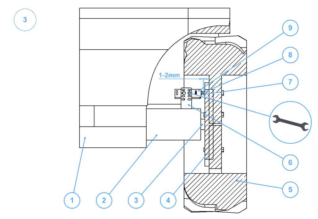
The speed sensor is an inductive proximity sensor that detects metal parts from a distance of 0.4 mm. This sensor is usually mounted to the sprayer frame or axle from the inside of the wheel. The sensor must be placed in the axis with the bolts (studs) and during hub rotation the gap between the sensor and the bolts should be between 1 mm and 2 mm. Correct sensor operations is indicated by the LED located in the sensor flashing during hub rotation. Every time the bolt approaches the sensor, the sensor LED should flash.
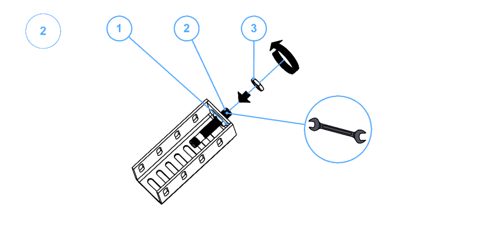
Figure 5.22 Instructions for speed sensor installation in the sensor bracket. Tighten the counter screws with a wrench, with no more than 2 Nm of torque. 1 – Lock nut; 2 – Inductive sensor; 3 – Lock nut;
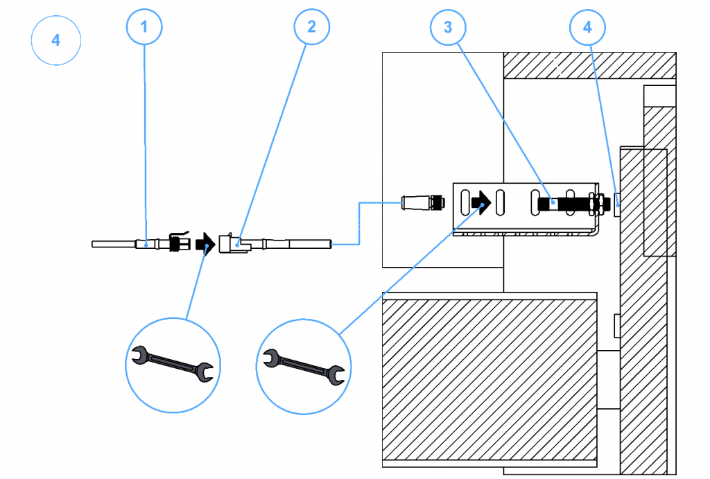
Connect the speed sensor to the three wires exiting the controller, according to their labeling or colors.
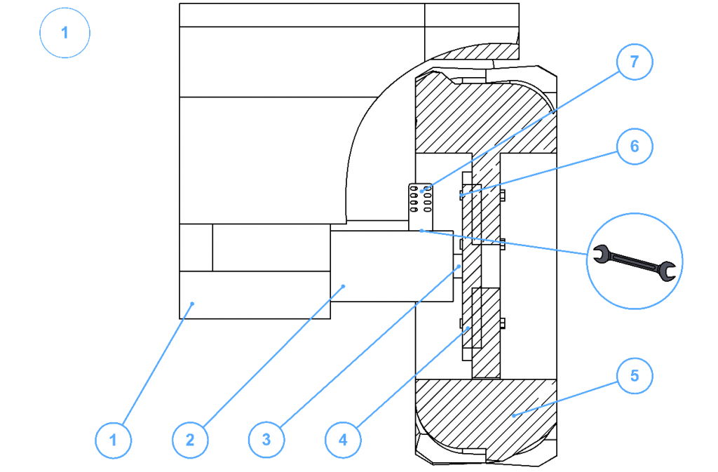
Figure 5.23 Instructions for mounting the speed sensor with its bracket near the wheel hub. 1 – Sprayer main body; 2 – Axle; 3 – Hub axle; 4 – Hub; 5 – Tire; 6 – Speed sensor mounting bracket part 1; 7 – Hub stud head; 8 – Speed sensor end; 9 – Speed sensor mounting bracket part 2;