Sprayer computer – home screen
The main screen consists of several so-called TILES, presenting different information from the sprayer.
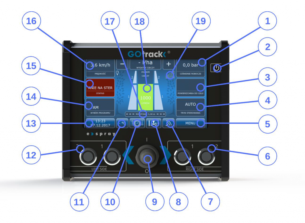
The central area (graphic area) of the main screen displays current information about the status of sprayer actuating elements. A graphical representation of the working liquid level in the tank is presented in the very center. By pressing this area, you can fill the tank with a pre-defined amount of liquid (read more in section 8.6 – Tank Filling).
Individual sprayer section are represented on both sides of the tank. Depending on the number of section chosen by the user at the configuration stage (read more in the Section Settings section), corresponding graphic indications will appear on screen. When activating and deactivating section, the color of these indicators changes from white to orange. The orange color indicates the section has been activated.
If the computer is equipped with a GSM modem, an antenna symbol will be visible on the right-hand side of the screen (reference 19 in Figure 7.1) with bars indicating the signal level. The more bars displayed, the better the signal.
On the left-hand side, there is a lightbulb symbol, allowing to activate and deactivate the sprayer fan attachment lighting, if available.
The Row Width button under the tank and sections visualization is used for manually selecting widths different than the one set by the operator in the spraying program. Row width is selected from the list of row widths pre-defined by the operator.
SPEED

Sprayer speed readings are displayed here. Additionally, depending on the row widths set in the alarms, this tile’s color may change to red, informing the operator that they have set an incorrect sprayer travel speed.
APPLICATION RATE

The value in this tile informs the operator about the current application rate in liters per ha (or another selected unit of measurement). If everything is working correctly, nozzles and filters are not clogged, the application rate during operation should be equal to the value set in the program.
The “-” and “+” buttons enable manual application rate corrections while the task is pending. If the operator identifies a need to increase or decrease the application rate over a small distance, they can introduce changes with those buttons. A manual correction (deviation from the uploaded program) will be signaled by the tile flashing green and an appropriate information under the application rate information.

This tile can also flash red if the alarm settings were configured and the application rate differs from the target value.
SPRAYING PRESSURE
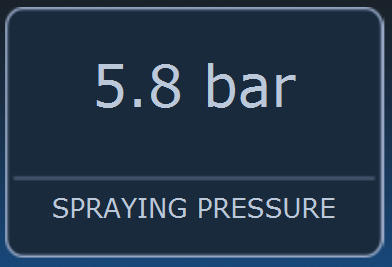
Spraying pressure displayed in this tile constitutes information retrieved directly from the pressure sensor. Additionally, this tile can flash red if the alarm settings were configured and the spraying pressure value exceeds the alarm thresholds.
In the MANUAL mode, the spraying pressure and application rate tiles change places. In the MANUAL mode, the operator changes the spraying pressure with the “-” and “+” buttons. Read more on this topic in the paragraph concerning switching from AUTO to MANUAL mode.

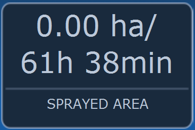
AREA LEFT
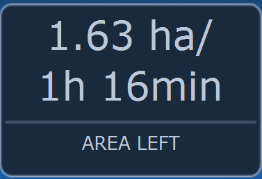
Information concerning the time and area that is still to be sprayed with the liquid amount left in the sprayer is provided here. In order for this information to be displayed properly, ensure proper program configuration: row width must reflect the actual value, the speed sensor must be calibrated properly and the correct amount of working liquid must be introduced during tank filling. If these conditions are met, the computer will provide real-time calculations for the time and area left until the tank is empty.
STEERING MODE
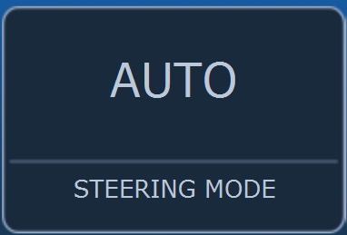
By pressing the “steering mode” tile, the operator selects the application rate control method: AUTO or MANUAL.
In the AUTO mode, the e-Spray computer adjusts the control valve in order to keep a uniform application rate (set in the program) per hectare of orchard area taking into account the real-time travel speed, row width and the number and type of nozzles. In the AUTO mode, the operator does not need to constantly control the spraying pressure to ensure that the operation is performed properly. This is done automatically by the e-Spray computer.

Please note that nozzles have individual application rate characteristics and therefore choosing a particular spraying program will only achieve the target application rate in a particular speed range. Too fast or too slow driving may result in the computer not being able to adjust the control valve to maintain the target application rate.
In the MANUAL mode, the operator sets the target spraying pressure using the “-” and “+” buttons, and the computer adjusts the control valve to maintain the target pressure. In this case, the sprayer computer does not take into account any program selections, but rather maintains the target pressure, disregarding travel speed, row width or power take-off (PTO) rotational speed.
TRACTOR AND SPRAYER AUTO MODE
This feature is enabled only if the complete GOtrack GPS tractor steering system was purchased. This means the e-Spray sprayer computer is compatible with the rest of the GOtrack system. You can add any missing system elements to your tractor in the future.
MAIN VALVE ACTIVATION

This tile presents the state of the main valve (activated or deactivated). By pressing it, you can activate the main valve without activating the sections (this is called “mixing mode”). In this mode, the valve is opened but the section valves remain closed (although they are ready to be activated).
When the mixing mode is activated, the mixing pressure is maintained. Set separately under MENU>PRESSURE>MIXING PRESSURE. The default pressure value is 5 bar. To exit the mixing mode, deactivate the main valve with this tile or by deactivating/activating the main valve using the joystick (upward or downward movement, respectively). If the mixing mode is activated, which means the main valve is open and the section valves are closed, moving the joystick upwards exits the mixing mode and enters the AUTO or MANUAL mode, respectively, and (if sections activation was requested) the selected sections will be activated.
CONTROL VALVE

This section only contains a presentation of the control valve operating method. A highlighted upward arrow indicates a situation in which the computer requests the operating pressure to be increased by opening the control valve wider.
A highlighted downward arrow indicates the opposite situation. Depending on the valve sensitivity settings, those arrows will be displayed more or less frequently. More on this topic is available in the following section: Pressure settings.
TEMPERATURE

As a standard, the e-Spray computer is equipped with an air temperature sensor; the temperature is displayed here. By pressing the temperature tile, the operator may set alarms to notify of exceeding the minimum and maximum temperature.
TIME AND DATE

As a standard, the e-Spray computer is equipped with a real-time clock (RTC). Following the initial system time and date setting, the computer will retain the time in memory even when turned off.
After longer deactivation periods (inter-season break), verify whether the clock indications are correct. Should the indications differ from the actual time, you can correct it under MENU>TIME.
After pressing the time and date tile, the screen brightness menu is displayed. The operator can choose from among three screen lighting levels, according to preferences. Section buttons lighting changes along with the screen lighting brightness.
SELECT PROGRAM
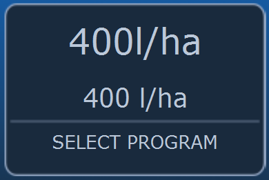
By pressing this tile, the operator enters a menu where they can select existing programs or create a new one. After a program is selected, the program name is displayed here on the main screen, along with the working liquid application rate per hectare of orchard area.
STATUS
The status of individual tasks is displayed here. The computer calculates the orchard area sprayed and the elapsed time for the current task since the counter reset.
By pressing this tile, you can access more detailed information on the pending task: distance traveled, average travel speed, sprayed area etc. At the bottom of the screen, there is a button for resetting the computer counters. After pressing the RESET button, the computer will reset previous counter readings.