Sprayer computer installation
Figure 5.3 presents the sprayer computer with descriptions of the individual elements.
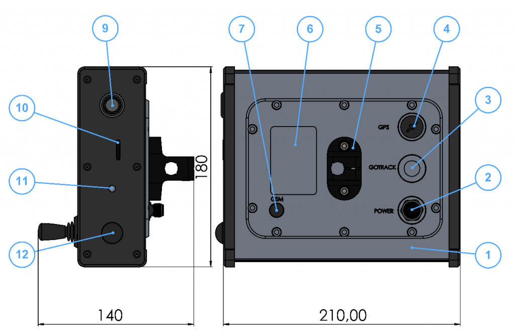
Figure 5.3 Sprayer computer with descriptions of external elements. 1 – Computer main body; 2 – M12 power socket; 3 – Location of the optional socket for tractor control system management; this option is available in the autonomous drive system; 4 – Location of the optional GPS Assist module communication socket; 5 – d12 rod bracket; 6 – Nameplate location; 7 – GSM antenna; 9 – Power switch; 10 – SIM card slot with plug; 11 – Piezoelectric signaling loudspeaker; 12 – Sprayer module communication antenna;
The device consists of two modules that communicate wirelessly. As shown in Figure 5.4.
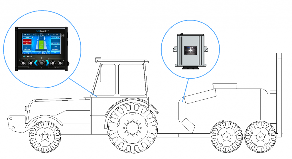
Figure 5.4 Computer and sprayer module location.
The computer along with the display should be installed at a convenient location inside the tractor cabin. Make sure the installation site ensures comfortable access to the computer buttons for the tractor operator, as well as good screen visibility. See Figure 5.5.
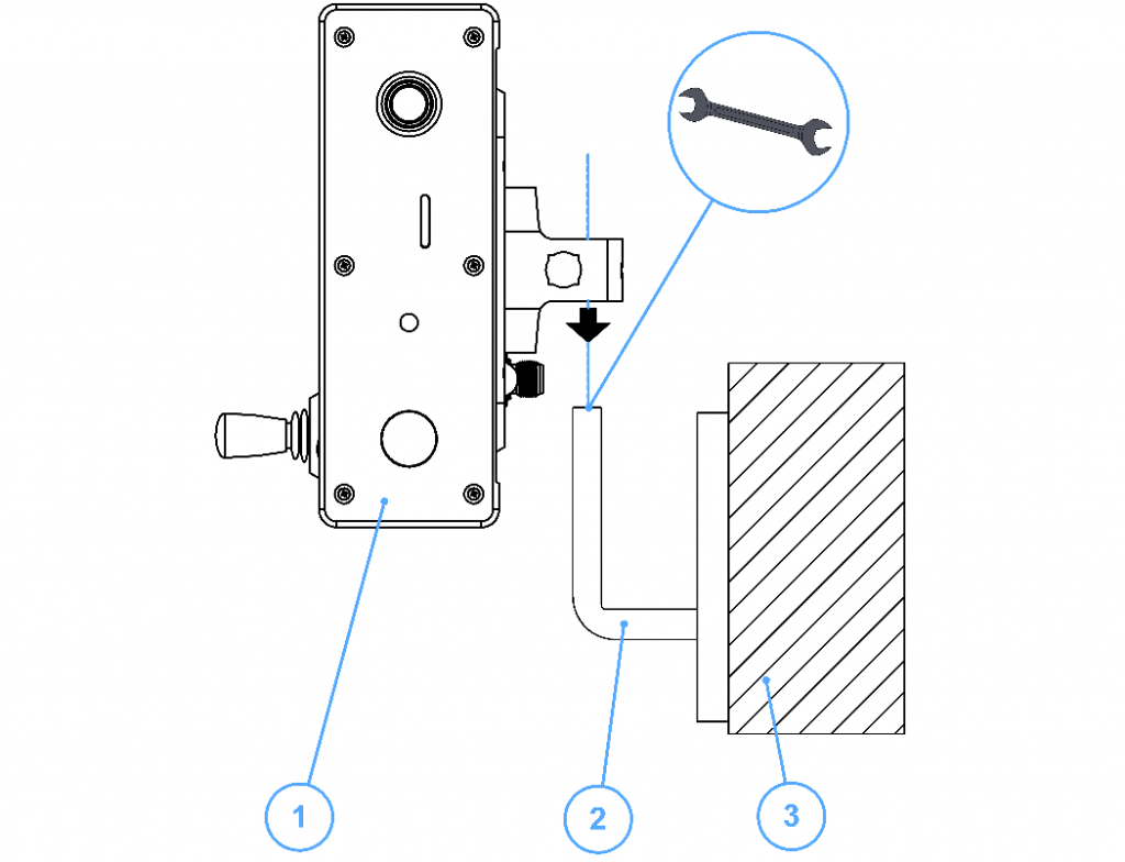
Figure 5.5 Installation of the sprayer computer on a previously prepared d12 rod. 1 – Sprayer computer – side view; 2 – d12 rod; 3 – Tractor main body;
Connect the sprayer computer to the previously prepared power socket. See Figure 5.1.
The power cord is terminated with a M12 plug. Insert the plug correctly into socket 2, as shown in Figure 5.2 and tighten the nut.